 |
|
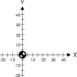
Normal coordinate system (Milling) |
To program a toolpath in a CNC application, the profile must be described to define the toolpath. This is done by defining points relative to the zero point of the coordinate system.
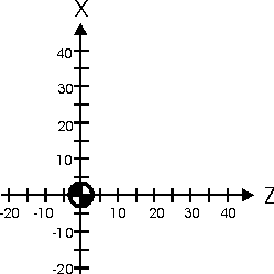
A coordinate system consists of 2 axes, which are perpendicular to each other and have a common zero point. Their positive directions are shown by the arrows. The horizontal line is usually called the X-axis or abscissa axis, and the vertical line is usually called the Y -axis or ordinate axis. The intersection point is called the zero point and is designated with a quadrant zero. When turning, the horizontal axis is designated with Z and the vertical axis is designated with X. This is called a Cartesian coordinate system.
When turning, the Z axis is always parallel to the main spindle.
|
|
Normal coordinate system (Milling) |
 |
|
Normal coordinate system (Turning) |
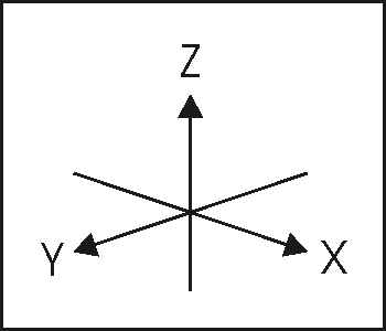
If you add an extra axis to the two, you have a 3D coordinate system used when milling.
 |
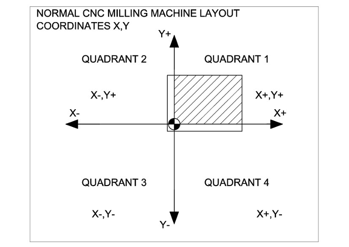
Quadrant 1: X values + and Y values +
Quadrant 2: X values - and Y values +
Quadrant 3: X values - and Y values -
Quadrant 4: X values + and Y values -
 |
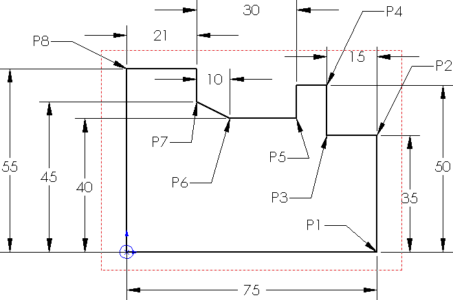 |
Look at the drawing above and find the X and Y coordinates for the following positions.
| P1 | X= | Y= |
| P2 | X= | Y= |
| P3 | X= | Y= |
| P4 | X= | Y= |
| P5 | X= | Y= |
| P6 | X= | Y= |
| P7 | X= | Y= |
| P8 | X= | Y= |